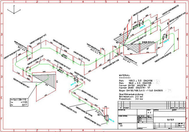


These are used by fab shops to create each individual spool as dgorsman mentioned. If you choose Spool drawing - you will end up with a single pipe spool per drawing based on the size criteria entered in the spool section. Isometrics are usually drawn from information found on a plan and elevation views. If you have selected "Iso drawing" - the spool section is used to define spools to be annotated within that iso, and consequently the Isos will split sheets at spool boundaries, but can contain multiple spools. Piping Isometrics Unlike orthographics, piping isometrics allow the pipe to be drawn in a manner by which the length, width and depth are shown in a single view. New field welds can be added to the iso if you specify the "place field welds at maximum pipe length" setting. New flanges or other components will not be added - we use what is modeled, but the piping will be split at existing flanges/field welds to ensure each spool is not bigger then the size specified. Its popular within the process piping industry because it can be laid out and drawn with ease and portrays the. How to draw piping isometrics in Autocad (Autocad tutorial) DesiGn HuB 191K views 4 years ago Piping Isometrics Symbols Preparation Examples Basic Engineering Piping. For example you can enter the size limitations imposed by your truck size for example to limit the spool size so that it can be transported. Drawing Isometric Offsets Calculating Isometric Offsets Isometric Dimensioning & Labeling Institute of Piping Engineering & Building Services - An isometric drawing is a type of pictorial drawing in which three sides of an object can be seen in one view. The Spools section you have highlighted in red in the image is where you adjust criteria to determine the size of a pipe spool.


 0 kommentar(er)
